


Product Description
The products implement the National Standard GB1094-2013 Power Transformer and GB / T6451-2015 Three-phase Oil-immersed Power Transformer Technical Parameters and Requirements, and are recommended as the major equipment products for the national urban and rural power grid construction and retrofit by the State Economic and Trade Commission.
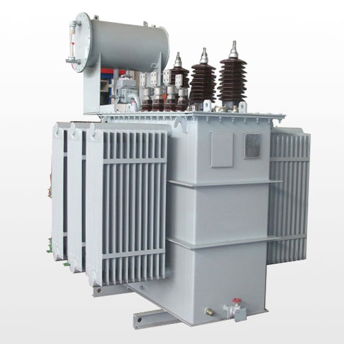
S11 series transformer adopts high quality material for copper winding, especially applying the new technology and new material for the coil insulation and active parts, thus the no-load and the load loss are obviously reduced, the performance and structure are more reliable and superior.
Product Features
●Good Economic Performance
The no-load loss for S11 series products decreased 10.3% averagely, no-load current decreased 22.4% based on S9 series.
●Long Service Life
Transformer tank adopts hermetical structure, tank and tank cover can be connected by bolts or welded firmly, the transformer oil won’t contact with air, so that extend the service life effectively.
●High Operation Reliability
Improve the relevant sealing parts for the tank, increase the reliability and advance the technical level to ensure the reliability of the seal.
●Small Installation Area
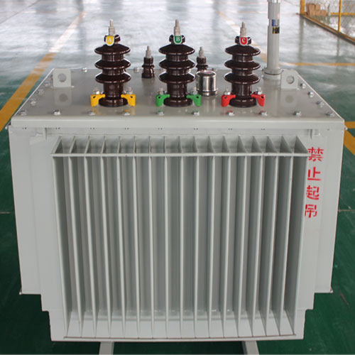
S11-M series transformer tank uses the corrugated plate radiator. When the oil temperature changes, the corrugated plate will proceed thermal expansion, which can replace the role of the oil conservator. the corrugated plate tank has beautiful appearance, less occupied area.
Model and Meaning
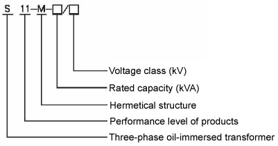
Table 1: 6Kv, 10kV & 30kVA-2500kVA Power Transformer With Off Circuit Tap Changer
| Rated Capacity (kVA) | Voltage Combination | Connection Group Symbol | No-load Loss R(W) | Load Loss R(W)75℃ | Impedance Voltage (%) | No-load Current(%) | Length L(mm) | Width W (mm) |
Height H(mm) |
Gauge Horizontal*Vertical (mm) | Active parts Weight(Kg) | Oil Weight(Kg) | Total Weight(Kg) | ||
| High Voltage (KV) | Tapping Range of High Voltage | Low Voltage (KV) | |||||||||||||
| 30 | 6 6.3 10 10.5 |
±5% ±2×2.5% |
0.4 | Dyn11 Yzn11 Yyn0 |
100 | 630/600 | 4.0 | 2.8 | 980 | 735 | 1145 | 400*400 | 178 | 78 | 355 |
| 50 | 130 | 910/870 | 2.5 | 1017 | 758 | 1205 | 450*400 | 240 | 92 | 415 | |||||
| 63 | 150 | 1090/1040 | 2.4 | 1035 | 785 | 1285 | 450*400 | 285 | 105 | 505 | |||||
| 80 | 180 | 1310/1250 | 2.2 | 1065 | 800 | 1290 | 450*400 | 330 | 110 | 540 | |||||
| 100 | 200 | 1580/1500 | 2.1 | 1072 | 820 | 1305 | 450*400 | 345 | 116 | 590 | |||||
| 125 | 240 | 1890/1800 | 2.0 | 1155 | 1105 | 1310 | 450*550 | 415 | 135 | 705 | |||||
| 160 | 280 | 2310/2200 | 1.9 | 1235 | 850 | 1535 | 550*550 | 485 | 155 | 835 | |||||
| 200 | 340 | 2730/2600 | 1.8 | 1282 | 860 | 1557 | 550*550 | 582 | 168 | 965 | |||||
| 250 | 400 | 3200/3050 | 1.7 | 1310 | 940 | 1605 | 550*550 | 695 | 210 | 1135 | |||||
| 315 | 480 | 3830/3650 | 1.6 | 1465 | 1120 | 1915 | 660*650 | 855 | 255 | 1520 | |||||
| 400 | 570 | 4520/4300 | 1.5 | 1440 | 1165 | 1725 | 660*660 | 950 | 295 | 1590 | |||||
| 500 | 680 | 5410/5150 | 1.4 | 1510 | 1250 | 1845 | 660*650 | 1150 | 320 | 1905 | |||||
| 630 | 810 | 6200 | 1.3 | 1650 | 1140 | 1920 | 660*650 | 1500 | 435 | 2015 | |||||
| 800 | 980 | 7500 | 4.5 | 1.2 | 2125 | 1175 | 2315 | 820*820 | 1910 | 760 | 3510 | ||||
| 1000 | 1150 | 10300 | 1.1 | 2150 | 1380 | 2570 | 820*820 | 2125 | 880 | 3850 | |||||
| 1250 | 1360 | 12000 | 1.0 | 2355 | 1485 | 2570 | 820*820 | 2605 | 960 | 4610 | |||||
| 1600 | 1640 | 14500 | 0.9 | 2385 | 1750 | 2630 | 820*820 | 3125 | 1150 | 5420 | |||||
| 2000 | 1940 | 18300 | 5.0 | 0.4 | 1940 | 1400 | 1700 | 820*820 | 2420 | 780 | 4200 | ||||
| 2500 | 2290 | 21200 | 0.4 | 2050 | 1480 | 1800 | 820*820 | 2560 | 880 | 4680 | |||||
Notes:
1.The Dimension and weight will be changed according to the requirements. These two data in the table will be subject to the factory documents.
2.For the transformer of rated capacity up to 500kVA, the value of load loss above the oblique line in the table is applicable to the connection group Dyn11 or Yzn11. The value of load loss under the oblique line is applicable to the connection group Yyn0.
Technical Parameter for S11 Series 20kV Power Transformer With Off Circuit Tap Changer
| (KVA)Rated capaci | Voltage Combination | Connection Group Symbol | No-load Loss(W) | Load Loss (W)75℃ | No-load Current (%) | Short-circuit Impedance(%) | ||
| High Voltage (KV) | Tapping ranges of High Voltage | Low Voltage(KV) | ||||||
| 30 | 20 | ±5% ±2×2.5% |
0.4 | Dyn11 Yzn11 Yyn0 |
100 | 690/660 | 2.1 | 5.5 |
| 50 | 130 | 1010/960 | 2.0 | |||||
| 63 | 150 | 1200/1150 | 1.9 | |||||
| 80 | 180 | 1440/1370 | 1.8 | |||||
| 100 | 200 | 1730/1650 | 1.6 | |||||
| 125 | 240 | 2080/1980 | 1.5 | |||||
| 160 | 290 | 2540/2420 | 1.4 | |||||
| 200 | 340 | 3000/2860 | 1.3 | |||||
| 250 | 400 | 3520/3350 | 1.2 | |||||
| 315 | 480 | 4210/4010 | 1.1 | |||||
| 400 | 570 | 4970/4730 | 1.0 | |||||
| 500 | 680 | 5940/5660 | 1.0 | |||||
| 630 | 810 | 6820 | 0.9 | 6.0 | ||||
| 800 | 980 | 8250 | 0.8 | |||||
| 1000 | 1150 | 11330 | 0.7 | |||||
| 1250 | 1380 | 13200 | 0.7 | |||||
| 1600 | 1660 | 15950 | 0.6 | |||||
| 2000 | 1950 | 19140 | 0.6 | |||||
| 2500 | 2340 | 22220 | 0.5 | |||||
Notes:
1.The Dimension and weight will be changed according to the requirements. These two data in the table will be subject to the factory documents.
2.For the transformer of rated capacity up to 500kVA, the value of load loss above the oblique line in the table is applicable to the connection group Dyn11 or Yzn11. The value of load loss under the oblique line is applicable to the connection group Yyn0.
3.The performance parameters in the table are also applicable for HV with dual voltage 20 (10)kV three-phase transformer.
Technical Parameter for S11 Series 35kV Power Transformer With Off Circuit Tap Changer
| Model | Voltage Combination | Connection Group Symbol | No-load Loss (W)75℃ | Load Loss R(W) | Impedance Voltage (%) | No-load Current(%) | Length L(mm) | Width W(mm) | Height H(mm) | Gauge Horizontal*Vertical (mm) | Active parts Weight(Kg) | Oil Weight(Kg) | Total Weight(Kg) | ||
| High Voltage (kV) | Tapping Range of High Voltage% | Low Voltage (kV) | |||||||||||||
| 50 | 35 38.5 |
±2×2.5% ±5% |
0.4 | Dyn11/ Yyn0 | 160 | 1200/1140 | 6.5 | 1.3 | 1195 | 935 | 1825 | 660*660 | 300 | 330 | 860 |
| 100 | 230 | 2010/1910 | 1.1 | 1200 | 995 | 1935 | 660*660 | 470 | 383 | 1130 | |||||
| 125 | 270 | 2370/2260 | 1.1 | 1235 | 940 | 1955 | 660*660 | 550 | 465 | 1335 | |||||
| 160 | 280 | 2820/2680 | 1.0 | 1285 | 895 | 1950 | 660*660 | 580 | 485 | 1475 | |||||
| 200 | 340 | 3320/3160 | 1.0 | 1310 | 1150 | 1985 | 660*660 | 680 | 595 | 1755 | |||||
| 250 | 400 | 3950/3760 | 0.95 | 1450 | 1090 | 2010 | 660*660 | 860 | 650 | 2000 | |||||
| 315 | 480 | 4750/4530 | 0.95 | 1930 | 1065 | 2320 | 820*820 | 980 | 765 | 2290 | |||||
| 400 | 580 | 5740/5470 | 0.85 | 1850 | 1165 | 2015 | 820*820 | 1170 | 885 | 2725 | |||||
| 500 | 680 | 6910/6580 | 0.85 | 2045 | 1205 | 2415 | 820*820 | 1340 | 960 | 3090 | |||||
| 630 | 830 | 7860 | 0.65 | 2085 | 1240 | 2515 | 660*660 | 1550 | 895 | 3810 | |||||
| 800 | 980 | 9400 | 0.65 | 2305 | 1615 | 2685 | 820*820 | 1990 | 1030 | 4510 | |||||
| 1000 | 1150 | 11500 | 0.65 | 2545 | 1540 | 2590 | 1070*1070 | 2415 | 1475 | 5055 | |||||
| 1250 | 1400 | 13900 | 0.60 | 2495 | 2010 | 2675 | 820*820 | 2480 | 1405 | 5290 | |||||
| 1600 | 1690 | 16600 | 0.60 | 2680 | 2100 | 2770 | 820*820 | 2600 | 1490 | 5450 | |||||
| 2000 | 1990 | 19700 | 0.55 | 2790 | 2180 | 2860 | 820*820 | 2720 | 1590 | 5600 | |||||
| 2500 | 2360 | 23200 | 0.55 | 2900 | 2290 | 2980 | 1070*1070 | 2830 | 1720 | 5760 | |||||
Notes:
1.The Dimension and weight will be changed according to the requirements. These two data in the table will be subject to the factory documents.
2.For the transformer of rated capacity up to 500KVA, the value of load loss above the oblique line in the table is applicable to the connection group Dyn11. The value of load loss under the oblique line is applicable to the connection group Yyn0.
S11 Series 35kV 630kVA-31500kVA Three-phase Dual Winding Power Transformer With Off Circuit Tap Changer
| Model | Voltage Combination | Connection Group Symbol | No-load Loss (W) | Load Loss R(W) | No-load Current(%) |
Short circuit impedance (%) |
Length L(mm) |
Width W(mm) |
Height H(mm) |
Gauge Horizontal*Vertical (mm) |
Active parts Weight(Kg) |
Oil Weight(Kg) |
Total Weight(Kg) |
||
|
High Voltage (kV) |
Tapping Range of High Voltage% |
Low Voltage (kV) | |||||||||||||
| 630 | 35 | ±2×2.5%±5% | 3.15 6.3 10.5 |
Yd11 | 830 | 7860 | 0.65 | 6.5 |
2400 |
1700 |
2210 |
820*820 |
2210 |
900 |
3250 |
| 800 | 980 | 9400 | 0.65 |
2500 |
1850 |
2390 |
820*820 |
2350 |
1030 |
3500 |
|||||
| 1000 | 1150 | 1150 | 0.65 |
2700 |
1950 |
2510 |
820*820 |
2490 |
1180 |
3860 |
|||||
| 1250 | 1400 | 1390 | 0.55 |
2900 |
2050 |
2630 |
820*820 |
2600 |
1350 |
4350 |
|||||
| 1600 | 1690 | 1660 | 0.45 |
3050 |
2130 |
2750 |
820*820 |
2810 |
1580 |
4855 |
|||||
| 2000 | 2170 | 1830 | 0.45 |
3105 |
2195 |
2805 |
1070*1070 |
2800 |
1800 |
5300 |
|||||
| 2500 | 2560 | 1960 | 0.45 |
3150 |
2535 |
2980 |
1070*1070 |
3525 |
2060 |
7665 |
|||||
| 3150 | 35-38.5 | ±2×2.5%±5% | 3.15 6.3 10.5 |
3040 | 2300 | 0.45 | 7.0 |
3920 |
2725 |
2840 |
1070*1070 |
3995 |
2205 |
8565 |
|
| 4000 | 3610 | 2730 | 0.45 |
3310 |
2915 |
3070 |
1070*1070 |
4825 |
2560 |
10115 |
|||||
| 5000 | 4320 | 3130 | 0.45 |
3480 |
3020 |
3145 |
1070*1070 |
5700 |
2635 |
11305 |
|||||
| 6300 | 5240 | 3500 | 0.45 | 8.0 |
3590 |
2905 |
3210 |
1475*1475 |
7120 |
3240 |
13510 |
||||
| 8000 | 35-38.5 | ±2×2.5% | 3.15 3.3 6.3 6.6 10.5 |
YNd11 | 7200 | 3840 | 0.35 |
4070 |
3050 |
3595 |
1475*1475 |
8875 |
3840 |
16690 |
|
| 10000 | 8700 | 4530 | 0.35 |
4106 |
2795 |
3655 |
2000*1475 |
10305 |
3600 |
17690 |
|||||
| 12500 | 1000 | 5380 | 0.30 |
4570 |
3010 |
3840 |
1475*1475 |
12830 |
4310 |
20990 |
|||||
| 16000 | 1210 | 6580 | 0.30 |
5235 |
3295 |
4615 |
2000*1475 |
16010 |
6650 |
27660 |
|||||
| 20000 | 1440 | 7950 | 0.30 |
5360 |
3415 |
4660 |
2000*1475 |
18820 |
7600 |
32170 |
|||||
| 25000 | 1700 | 9400 | 0.25 | 10.0 |
5830 |
3810 |
4860 |
2000*1475 |
22360 |
9800 |
42600 |
||||
| 31500 | 2020 | 112000 | 0.25 |
6290 |
4290 |
5260 |
2000*1475 |
25110 |
12010 |
49960 |
|||||
Note: 1: For the transformer of low voltage 10.5kV, the connection group symbol is applicable to Dyn11.
Note: 2: For the transformer of rated capacity 3150kVA or above, the -5% tapping position is for maximum current tap.
Note: 3: When the annual average load rate for the transformer is between 35% to 45%, the loss value in the table can obtain the highest operational efficiency.
 Downloads:
